
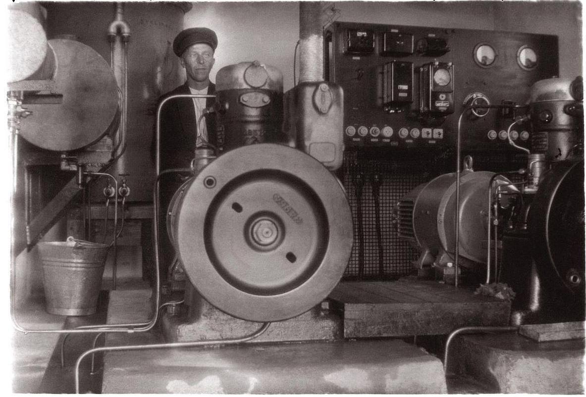


When the air ligth beacons were built in 1937, there were no electricity power
lines to the islands Kumlinge in Åland and Iniö in Finland. Hot-bulb engines and generators
were used to get electricity to the beacon lamps (55 Volt, 1500 Watt) and rotation motors.
Old photos from Kumlinge are available thanks to Lauri Åkerblom who leads
a Photo Project on Kumlinge and has scanned almost all old photos in farms and homes on Kumlinge.
And among those there are some 20 photos from the air light beacon. One very unique photo is the one
below taken from inside the generator house.
It contains two Skandia 21S hot-bulb engines with generators.
What about the different parts in the machinery?
Östen Runelind, L.Laurin, wrote and pointed out that the small tank ought to
be for lubrication oil, since it connects to the lubrication oil pump (type ÅSSA).
His guess is that them medium size tank is for oil cleaning, and the largest for fuel.
My own guess is that the medium sized tank is for fuel (may hold 150-200 litres), and the largest one for cooling of water.
- Anyone who knows more?
| Photo from Lauri Åkerblom. Texts by Bo Ju. Comments are welcomed. Click for larger image. | |
 
|

|
The hot-bulb engine was an early type of combustion engine.
It is somewhat simpler than the Otto-engine (petrol engine) and Diesel-engine,
in having no ignition system (generator, ignition coil, distributor, spark-plugs) and no
guided ports (camshaft, valve rods, valves).
It was produced in large numbers in early 20th century. Factories in Sweden were e.g.
Pythagoras in Norrtälje (see beacon 143!) and Skandia in Lysekil (ship engines).
Hot-bulb engines are two-stroke engines where fuel ignites inside a small hot chamber on top of
the cylinder. Cooling is important since the cylinder must be cool and the bulb hot - it was heated with
a blowtorch before start. The drawing below does not show some parts of the system: fuel pump with regulator,
water pump, flywheel.
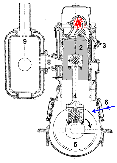 |
Left: Stroke 1. As the piston moves upwards, the air-fuel mixture is compressed
in the glowing bulb 1 and explodes. The high pressure forces the piston 2 and
piston rod 4 down. Fuel is inserted by a pump at 3. When the piston moved up,
air was sucked into the crankcase through air intake 6. Right: Stroke 2. When the piston reaches its lowest position, the exhaust port 8 opens and gases move to silencer and exhaust pipe 9. The air in the crankcase was compressed when the piston moved down (there is a simple back-valve on the air inlet) and as the inlet port opens the compressed air flows through channel 7. Crankshaft 5 has a balance weight. And on the outside a heavy flywheel. Power is transmitted using a belt pulley or directly, as for the generator. Base image from Wikipedia, reworked by Bo Ju. |
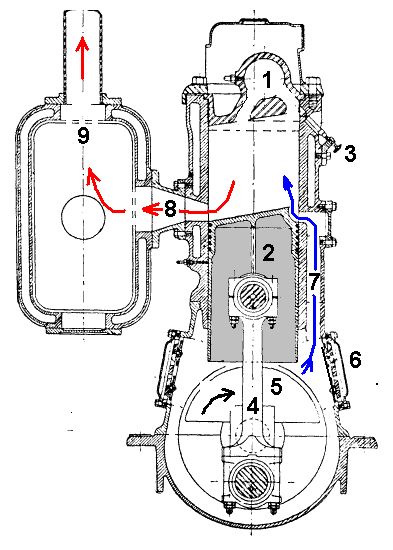 |
There are many images and videos with hot-bulb engines on internet. You can find them by searching
on Google. Here a link to a video with a hot-bulb engine with generator, of the same type
Skandia 21S that was used in Kumlinge. If you listen to the sound of this engine and other hot-bulb engines,
you can hear that Skandia 21S had higher rotation speed!
›
Click to start this Youtube video recorded by hotbulbman, but where and who?
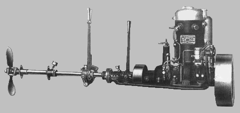
Engine model 21 from 1920 weighed less and had higher rotation speed
than earlier hot-bulb engines. It had roll bearings.
Models 21A and 21B was for use in boats, e.g. fishing vessels,
21S was stationary, and combined with generator named: KKG.
- Weight 160 - 220 kg depending on model, thereof which därav svänghjulet ca 50 kg.
- Cylinder diameter 120 mm and stroke length 90 mm.
- Engine power 4/5 hp at 800/1000 rpm.
- Fuel consumption 290 gram per hp/hour.
The engines for the air light beacons thus was a 21S with KKG,
and its 2-3 kW consumed 1-1. litre/hour, 10-15 litre/night.
Photo of Skandia 21 boat engine, photo from LLaurin.se
|
Details: Fuel pump and regulator, with pipe to hot-bulb. 
|
Lubrication oil pump type ÅSSA. 
|
Bo Justusson, Stockholm
Contact: justusXownit.nu - switch X to @
Last update: 29 April, 2012